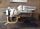
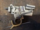
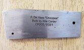
Scratch Built Single Shot (Completed Jan. 2022)

cold1

Member
2A Bourbon Hound 2024
Benefactor
Supporting Member
Multi-Factor Enabled
Joined
Dec 19, 2016
Messages
2,548
Rating - 100%
9   0   0
With Fall and Winter setting in, I decided that i wanted to build another of the DeHass Chicopee single shots. Ive been wanting a 22 Hornet so I think thats what this on will be. I ordered the steel a couple of weeks ago and started cutting things out this weekend. The last one took a little over 3 years to build. During that time i had to acquire some tools, tooling, and a whole lot of knowledge. I initially thought about building one of the other actions he has in the book "Mr. Single Shots Book of Rifle Plan", after a tremendous amount of inward reflection i decided that I didnt do too great on the first Chicopee and that i should focus on producing a better one of those before trying something more advanced. More of a crawl, crawl some more, walk, walk some more, RUN philosophy ;)

The thing about this rifle plan is that is a 1:1 template for the drawings in the book. You print the drawings out and use them as a pattern for your cuts and shaping. This way may be upsetting to some real Machinist since there are not a lot of dimensions given in these drawings, but that is how DeHass wanted it. You dont have to be a master machinist to make it.

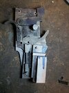
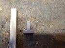
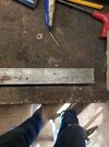
Lets start with the raw Cold rolled stock R-L: 1/4 x 2, 3/16 x 1 1/2, 1/8 x 1, and 1 1/8 x 1 all are 12 inches long.

20201011_122125.jpg

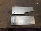
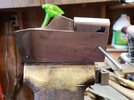
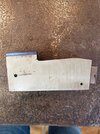
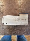
The first thing was to rough out some parts on the bandsaw. I started with the action side plates. Once i hade them roughed out, i drilled both sides for locating pins and pinned them together. I performed all the machining to them while they are pinned so that both half would be identical. I did the swinging block the same way.

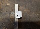
Action Side plates top, Swinging block bottom.

20201014_155804.jpg


Because this is a Swinging block design, the block travels in an arc of a circle. The back of the swinging block needs to be radiused. The pin location on the front (narrow) end of the block is the pivot pin location. The plans do call for a measurement of 3.82ish inches from the pivot to all points on the radiused end of the block. To get the radius that i needed, i secured a piece of angle iron in the mill vise and drilled/reamed a hole for the temporary pivot pin to be in. I placed a grinding wheel in my mill head and started grinding the radius.

20201014_155842.jpg

Thats all i have for now. There should be more coming, i just have to figure out how to sneak out of the house in the evenings. :p
 
The plans do call for a measurement of 3.82ish inches
woah! Can't keep up with all that machinist measuring there!!

Looking forward to this sequel thread.
 
Last edited:
Cool project.

One process question from a non-machinist, why did you decide to grind the radius vs use an end mill to cut it?
 
Cool project.

One process question from a non-machinist, why did you decide to grind the radius vs use an end mill to cut it?

Depends on what the radius is. There may not be a standard end mill that works, and a one-off custom end mill is an expensive proposition.

I very much like this little project, and I've always thought that the .22 Hornet is a neat little cartridge. Enough for most uses within its range limitations without overstating the case.

I’m developing an appreciation for the little hornet.

I just realized that the answer to my question is probably not about the cutter but about the fixture. Without a rotary table there wouldn't be a good way to drive the workpiece into a cutter, but with a grinder you can do it by hand.
 
I’m developing an appreciation for the little hornet.

I just realized that the answer to my question is probably not about the cutter but about the fixture. Without a rotary table there wouldn't be a good way to drive the workpiece into a cutter, but with a grinder you can do it by hand.

You are correct, I dont have a rotary table so I can't mill the radius in. I could use a faceplate for the lathe and clamp the pieces in and cut the radius that way but I don't have one of those either. With this grinding setup on the mill, I can feed the piece in a controlled amount and then swing it back and forth by hand.
 
woah! Can't keep up with all that machinist measuring there!!

Looking forward to this sequel thread.

Thats what I like about this rifle design. I think its great for a beginner like me. The plans are cut then fit, where most all others I have come across is cut to fit. Its pretty discouraging to spend a few hours making a part only to find out your a few thousand off one way or another and it won't fit. This design has a lot of room for errors that are easy to correct without having to start over.
 
Made a little more progress today in the shop. I started on the support shoulders. These are the parts that will be welded to the action side plates and take the bolt thrust when the cartridge is fired. This keeps the hinge pin from taking any force at all.

I ran into the first snafu, the diameter of the grinding wheel doesnt match the radius of the curve needed. I had to use the swinging block radius to mark the radius needed and then work the X and Y to grind close to the line.

20201015_155204.jpg

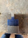
There was not a lot of contact between the freshly ground sholders and the swinging block when i held them in position. Lots of light coming through. I broke out the valve grinding compound and mad a little jig so that i could lap them together.

20201015_162556.jpg

Apply compound on the surface, tension the screw and swing away. Wash, rinse repeat. It went rather quickly with nothing but armstrong power. I cleaned everything off and checked my contact pattern.

20201015_162543.jpg

A little while later and another 15 minutes of lapping.

20201015_164112.jpg

Cell phone camera distorted the pic so the plates look curved downward. They are flat though.

Another 20 -30 minutes of lapping and i had about 90% contact. I pulled everything apart and started checking fit with back lighting.

20201015_165744.jpg

There is a small gap on the left side. I tried to measure it but me smallest feeler was .001 inch and it wouldnt fit. This will be very close to the same orientation of the parts when the action is fired. I think it will be good for the 22 Hornet pressures.
 
I've been working on it a little here and there. I got most of the parts made. Its now down to the piddly stuff of fitting each part.

I'm waiting on a 4 jaw chuck for the lathe so I can bore the receiver ring. Once that's done, I can weld the receiver up.

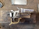
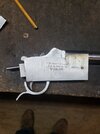
Here is a pic of the internals and how the fit together.

20201105_171955.jpg
 
Just a little update, I've been expirementing with some different things with this build and making some modifications. One thing I did not like was that the extractor was sprung on one side only and that it was also activated on one side only. I drilled and reamed holes on both side of the action for the extractor spring and the activating studs.

I also played with the size of the hole in the receiver ring for the barrel. I bored the hole out for a 5/8 thread. After I did that I started looking at it and doing some math and didn't like the idea of the thinner barrel walls for a 47000psi round. If I had made the receiver ring out of 4140HT I think I could have gotten away with the 5/8 size barrel shank. Since the ring is CRS, I decided to bore it out for 3/4 16 threads and barrel shank. That way there is less CRS and more 4140 of the barrel.

I dont like the way FDH makes the two piece breach face so I machined a T shaped piece out of CRS. I did this on the previous rifle too. My machining skills were lacking and there was a taper of .004 on the piece that is sandwiched between the two swinging action pieces. This created a problem when assembled so I am making another one using a different way to mill it. It came out without a taper.

I also decided that I didn't like the blocky looking receiver ring, so I rounded over the top corners with a 1/2 radius bit. There is still a flat spot on top if I need to mount scope bases.

I probably going to make a few more modifications, not that it will help the action but to push my limits a little more. I will get some pictures in the next few days. I'm sure that will help everyone follow what I'm talking about with these mods.

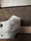
First up is the modified receiver side plate. Its nothing major, i wanted to get away from the little jog in the original plans so i wouldnt have to fit the forearm in that space.

The original is on top and the modified is on the bottom. The angle on the bottom of the modified piece is the same as all the way across. The top edge is the reference edge. It is the factory edge of the CRS.


receiver sides.jpg
 
Last edited:
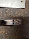
I do not like the two piece design that the book calls for. This is the one with the taper on the center section. I also dont like the idea of an 1/8 pin holding the breach face piece in the action, so drilled and tapped the swinging sections for a 8X32 shoulder bolt. This will hold both sides and the breach face in.

Here is the side view. The hole is offset 0.0005 to the right. I did this to help draw the breach face tight to the swinging actions sides.

Breach Face 1.jpgBreach Face 2.jpg
 
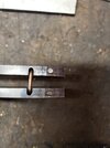
This the extractor system modification. Starting from right to left, the right most set of holes are for the extractor studs. (installed). These studs provide the force to move the extractor. the Plans call for just one stud.

The next set of holes are for the extractor spring plunger. This provides the upward force for the extractor. The Plans call for a single plunger and spring. I drilled two 1/8 holes 0.600 deep. I then milled a slot 1/8 wide and 0.130 deep. I did not want two independent spring plungers. I will be using a U shaped Bar instead. Springs on both legs and the milled recess is to allow it to lay flush when compressed.

Extractor spring Mod1.jpgSwing block mod 1.jpg
 
And finally, the start of a new breach face that doesnt have a taper. This is the center of the Tee. 0.255 wide to allow for some clearance for the moving parts like the hammer.

The plans call for a 1/8 piece to be attached to a 1/4 piece by a 6X40 screw. The 1/8 piece will be the breach face and the 1/4 will form the center section of the Tee.

I am going to make the breach face 0.25 thick on this. I think thicker is better. I also want to try to make a Neider style firing pin bushing and add some gas ports to help if i have a ruptured primer.

New breach block.jpg
 
2/22/2021 UPDATE

I havent had much time to work on this one the last few months. What time i did have i spent making some modifications to things i didnt like about the original design. I dont care for how the hammer spring or the locking latch spring worked.


In a pic above you can see the original hammer spring setup. It consisted of the spring and 3 separate pieces and relied on the pivot pin to hold everything together. Installing the 3 piece setup was interesting to say the least, i had to chase parts more than once when something didnt sit right and everything went flying. I decided to make a self contained captive hammer spring. I had to go through a few iterations of the design before i figured out what worked and what didnt. The new captive hammer spring is made up of a captive plunger, plunger bushing, springs, and top screw. The body is a piece of 1/4 inch drill rod that i bored and threaded each end to 12x24 thread. Its a little odd thread, i did try with a 10x24 thread but that diameter did not leave enough room for the springs i needed.

The original design for the locking latch spring was nothing more than some counter bored holes in the latch and the stock mounting block so the spring could fit in them. i did basically the same thing as i did for the hammer spring. The travel of the locking latch is almost 1/2 inch and all the spring has to do is push the latch forward and hold it there. I doesnt have to be a strong spring.

I took a few pics to show how the action operates.

This first one is the action closed and the hammer at rest. (to the right you can see one of the failed iterations of the hammer spring)


20210222_155148.jpg


This is the action closed and at full cock.


20210222_155217.jpg


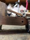
This is the action open and the extractor in the extracting position (the extractor isnt finished yet, here it is just a piece of 1/8 CRS flat stock)


20210222_155709.jpg
 
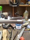
I get barrel blanks from Green Mountain barrels. These are drilled and rifled but left unfinished. This one is a 22 cal barrel with a 1 in 14 twist. I felt that twist with the 22 hornet will give me the most stability over a wide range of projectile weights and velocities. I am planning to shoot mostly cast bullets at mid velocities out of this.

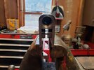
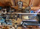
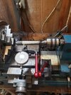
Here is my janky setup for turning the contour of the barrel. I turn between centers for concentrically to the bore. This little setup isnt a very good lathe, it lacks a lot of rigidity and it has other issues, but it is what i have so i make it work. I have only done 3 barrels on it and each has been interesting. The biggest problem with this particular barrel is the harmonics while turning. It sings and the singing leaves vibration marks in the barrel. I tried several different speeds, feeds, tools and grinds on the tooling and they all helped a little but it is still an issue. I think i am going to pack the barrel with lead shot and see if that helps eliminate the singing marks.

Anyway, here is a pic of the setup. Did i mention that my bench space is limited 😉

20210222_155828.jpg
 
Slow going, I haven't had much time to dedicate to it. Last weekend I got a fee hours and got the extractor slot cut and the extractor finished. I'm hoping to get it welded up soon. Once that's done, I can drill for the firing pin and chamber the barrel.
 
Welded up the receiver ring to the frame sides this morning. The first round of TIG went well, improvised a disk sander on the lathe and ground the weld beads down. Found i had some under cuts and washout, and went to fill them back in. I didn't think about the sanding contaminating the area when power sanding. I ended up with little craters everywhere in the second round of welds. I decided to stop there before I made things worse.

I moved on to trying to get the barrel screwed in. The welding distorted the hole too much. I ran the tap down the hole and cleaned most of it up but the unthreaded part of the tenon was digging in. I tried my hand at using the boring head to clean up the hole, but decided that using the boring head for this was beyond my skillset.

Now I have an adjustable reamer on order and a set of carbide burrs. The reamer is to make the hole round again and I'm going to use the burr to eat down to clean metal on the craters. Once I get down to clean metal, I'll be able to fill in those areas with weld and clean them up.

20210329_093616.jpg20210329_093608.jpg
 
Sounds like a frustrating session... or two. Thanks for the straightforward posting - it helps us Future Emulators (aka wannabees) understand the necessity of perseverence!
 
Sounds like a frustrating session... or two. Thanks for the straightforward posting - it helps us Future Emulators (aka wannabees) understand the necessity of perseverence!
Well that's part of learning on your own, you've got to have patience. When I started attempting to build the first one several years ago I had no machining experience, no welding experience, no real gunsmithing experience, I think you get the idea. I expect to make mistakes everytime I go to the shop and work on this project, I do expect not to make the same mistake twice though. So far I've haven't yet. I count that as a win.

I think this will be the last of these actions I build. I have found others that are more interesting to me and I want to try to build those.
 
May 14th update

Since the last post, I did ream the receiver ring back to round where the barrel will screw in. The idea of grinding down the bad spots in the welds and filling them back in didn't work ti well. I guess whatever contamination was in the welds was in there good because when I tried to fill the divots in after grinding them out, it just bubbled up again.

I had a little trouble with the barrel, when I was cleaning everything up on the sander I took just a little too much of the front of the receiver. The barrel would screw in too far and I couldn't close the action and the extractor didn't line up anymore. I took the lazy way out and made a 0.005 shim washer to fit between the barrel and the receiver. It worked great and you can't see it.

Next came the trigger guard. The book tells you to braze or weld it to the action side plate. I welded it on the last one I made and it was a PITA to get the welds ground and finished so the two action plates could fit together. I decided to screw and pin this one. Then came the fun part of making it. It started like as a rusty piece of 1/2 x 3 wide scrap. The bandsaw was used to rough it out. I used a boring head in the mill to make the inside radius. More trimming in the bandsaw and a little playing on the improvised disk sander and I now have a trigger guard that I'm happyish with.

20210514_204102.jpg
 
Most of the rifle metal work is done as far as fitting, smoothing the action, and getting everything to work the way it should. A few things left to do are case hardening the breechblock, trigger, and hammer. Got to fit the firing pin too.

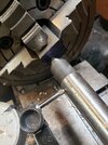
I decided to start trying to add accessories and push myself on making parts and machining. I started by making a barrel band with sling stud attachment. It took a little while and had to make some fixtures to work with it on the lathe.

Once I worked out the kinks on that I decided that I wanted a ramped and banded front sight. I started on that this morning. It took longer than it should have but with limited tooling it is what it is.

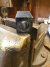
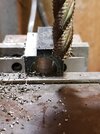
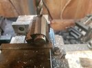
I started with a 1x1x2 block of cold rolled. I did the math and laid out the lines. Once the center of the hole for the barrel was marked, the fun started with the drills and reamers.

There are several ways for me to screw this up, so if it doesn't work out I won't be too surprised.

Starting block of steel.

20210523_090938.jpg


I made a hole 😁

20210523_113133.jpg


To Be Continued, I got to work on the storage building I'm building.
 
Last edited:
I take it that's neither my imagination nor a trick of photography saying the two centerlines aren't exactly a match? :(

EDIT: or that gap at the bottom ain't intended...
 
Last edited:
I didn't have the block of steel as square to the drill as I thought. The bottom of the hole has 0.030 off center.

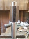
The piece that its mounted on in the pic is an arbor that I made that is needed for the next process in making the sight.

I'll be starting this piece over and checking my setup for drilling better next time.
 
Let's try again.

I started with a different piece this time. 1.25x1x2. I'm shooting for a 0.070 wall thickness.

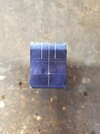
Layout and center punching.
20210527_190707.jpg

How do you center an offset hole in a 4 jaw chuck?

20210527_191100.jpg
 
Last edited:
Back
Top Bottom