Subpanel questions

surrealone

Well-Known Member
Benefactor
Life Member
Multi-Factor Enabled
Joined
Jan 26, 2021
Messages
2,150
Location
Semora, NC
Rating - 100%
10   0   0
Hi,
I'm hoping someone familiar with the NEC can shed some light on things that are unclear to me in the NEC regarding subpanels.

I am interested in adding two subpanels to my main panel. I do not believe the NEC precludes this, provided the following requirements are met:
  1. Sizing: The size of the main panel must be large enough to handle the combined loads of all subpanels.
  2. Ampacity: The ampacity of the wire between the main panel and subpanels must be appropriate for the total combined load and the distance traveled.
  3. Overcurrent protection: Each subpanel must be protected by an appropriately sized circuit breaker or fuse in the main panel.
  4. Grounding: All subpanels must be grounded and bonded to the main panel.
  5. Location: Subpanels must be located in a safe and accessible locations.
  6. Labeling: All subpanels and their breakers must be properly labeled to indicate their intended use.

My questions are:
  • What does it mean for subpanels to be grounded and bonded to the main panel? Is this just a connection from a main panel's ground bar to that of the subpanel, or is there something more required -- like separation of the neutral and ground bars in the subpanel (unlike in the main panel, where they are typically connected via a bus bar)?
  • What is expected of the breaker labeling to indicate intended use? Does the NEC want this label for the subpanel breaker (within the main panel) actually ON the breaker, itself ... or is an indicator in the main panel (e.g., inside the panel door) sufficient?

Any informed assistance is appreciated, thanks!
 
Last edited:
As I understand it, code requires a single point ground at the location, and this is typically off of the main panel. All wiring to 240V sub panels must be 4 wire. Two for the hots, one neutral and one ground. The neutral buss and the ground buss are bonded together at the main panel, wheras all sub panels must have the ground and neutral buss isolated from one another in each sub-panel.
 
Last edited:
@Scsmith42 nailed it. The bonding means that the neutral and ground connections must be continuous (not broken) back to the main panel. As you pointed out they get bonded at one place, in the main panel. The reason is that this way, the ground and neutral are held at the same potential (voltage) but that under normal circumstances current does not flow through the ground wire. All current that flows out of a source, think hot wire through a breaker will return to the source. With the ground circuit left 'open' no current will flow on it. If you were to bond the neutral and ground together in both the main panel and the sub panel, the two wires would be in parallel and the return current would split between them, which isn't what you want.

As far as labeling, in the main panel, simply write on the label, usually on the cover, "sub panel 1" or "SP1" or someting like that. In the sub panel, label it for whatever it is servicing - e.g. garage lights.
 
@noway2 -- thank you kindly, sir -- that makes sense -- we don't want electrocution potential via a secondary return path. Much appreciated on the labeling clarification.
 
Last edited:
And ... a follow-up pair of questions:

Context:
Since my last set of questions, I have procured a 100 amp panel that is suitable for use as a subpanel ... and a two-pole 100 amp breaker to go into my main panel (from which the subpanel will be fed). This is well more than I need, but I got both on the cheap, and the new panel matches my ancient old panel in terms of manufacturer and the breakers it accepts.) I know I need 4-conductor wire as a feeder, and adherence to the 80% rule for ampacity at 75C would indicate that #1 copper wire should be used ... on a 10ish foot run.

1) Does the above wire choice sound sane/correct? (i.e. Someone mind double-checking me?)
2) Where the heck is a good place to get #1 SER 4-conductor copper wire?

Note: I don't want to mess with THHN in conduit, as plumbing conduit to the main panel would be more work than running SER given the locations involved AND the fact that this won't be exposed when completed.
 
Last edited:
Have a read here: https://www.ecmweb.com/national-ele...zing-circuit-protection-and-conductors-part-1 If you search for the verbiage "Sizing Circuit Protection and Conductors" on that page's search function, it will pull up multiple parts to the document.

Unfortunately, this is where the question you are asking becomes a little bit difficult. In order to properly answer it, you need to know things like what the maximum ambient temperature is, and an idea of what the load is going to be and if any of it is defined as continuous, meaning in operation for three hours or more. However, you are likely correct that a 100A feed is going to be more than sufficient for the sub panel. Obviously, you will have downstream breakers as you will need protection for the smaller wire size. Having breakers on both ends, makes the wire you're sizing now into a feeder, which has different rules and is discussed in part two of the blog I linked to above.

One comment I will make is that I you chose the 75C table for the ampacity rating. This is acceptable IF and ONLY IF the connectors on both ends are explicitly rated for 75C, and if not or it's unknown you must go with the 60C table, which from the table I am looking at for SE cable rating would put you in 1/0 (assuming copper). Here's the link (check the specs tab - there is another caveat): https://www.southwire.com/wire-cable/building-wire/copper-service-entrance-ser-cable/p/BW6

Unless the is marked for use at higher temperatures the conductor ampacities shall be limited to the following per NEC 110.14(C) 60 ° C When terminated to equipment for circuits rated 100 amperes or less or marked for 14 - 1 AWG conductors
Which reads to me like the fact that you're running a 100A circuit, you may be limited to the 60C column. Edit - I think this goes back to what I said about everything having to be labeled as rated for higher or it defaults to 60C.

The good news is that SER cable looks like it is suitable for use in your application: https://www.wireandcableyourway.com/blog/using-ser-cable#:~:text=Using SER Cable to Feed Distribution and Sub-Panels,heavy-duty workshops 4 pool houses 5 green houses

As far as where to get it, you may be able to get it at a big box retailer like Home Depot or Lowe's. Failing that, I would look for an electrical supply like City Electric.
 
Last edited:
Have a read here: https://www.ecmweb.com/national-ele...zing-circuit-protection-and-conductors-part-1 If you search for the verbiage "Sizing Circuit Protection and Conductors" on that page's search function, it will pull up multiple parts to the document.

Unfortunately, this is where the question you are asking becomes a little bit difficult. In order to properly answer it, you need to know things like what the maximum ambient temperature is, and an idea of what the load is going to be and if any of it is defined as continuous, meaning in operation for three hours or more. However, you are likely correct that a 100A feed is going to be more than sufficient for the sub panel. Obviously, you will have downstream breakers as you will need protection for the smaller wire size. Having breakers on both ends, makes the wire you're sizing now into a feeder, which has different rules and is discussed in part two of the blog I linked to above.

One comment I will make is that I you chose the 75C table for the ampacity rating. This is acceptable IF and ONLY IF the connectors on both ends are explicitly rated for 75C, and if not or it's unknown you must go with the 60C table, which from the table I am looking at for SE cable rating would put you in 1/0 (assuming copper). Here's the link (check the specs tab - there is another caveat): https://www.southwire.com/wire-cable/building-wire/copper-service-entrance-ser-cable/p/BW6


Which reads to me like the fact that you're running a 100A circuit, you may be limited to the 60C column. Edit - I think this goes back to what I said about everything having to be labeled as rated for higher or it defaults to 60C.

The good news is that SER cable looks like it is suitable for use in your application: https://www.wireandcableyourway.com/blog/using-ser-cable#:~:text=Using SER Cable to Feed Distribution and Sub-Panels,heavy-duty workshops 4 pool houses 5 green houses

As far as where to get it, you may be able to get it at a big box retailer like Home Depot or Lowe's. Failing that, I would look for an electrical supply like City Electric.
I suppose I should have added more data/context, as:
  • Both panels are rated for "60C/75C" (it's shown exactly like that with the / between in the panel info)
  • The 100A (main) breaker in the subpanel states "75C CU/AL wire only"
  • The 100A two-pole breaker intended for the subpanel states "CU-AL 75C wire"
This is how I arrived at 75C and why I think I'm gtg with 75C 4-conductor #1 copper SER wire (when cross-checked against an ampacity/wire gauge/wire type chart). With that new info, do you concur?
 
Last edited:
Copper #2 is good for 100 amps service cable when all terminals are rated at 75°. Most calculations are done at 60°. Lowe’s has the cheapest wire.
 
Copper #2 is good for 100 amps service cable when all terminals are rated at 75°. Most calculations are done at 60°. Lowe’s has the cheapest wire.
(NEC 220-2) states: Maximum loading for any branch circuit is 80% of the rating of the circuit for ampacity of wire for any load.
I've been (perhaps erroneously?) presuming my feeder from the main panel to the sub panel would also be considered a 'branch' from the main panel ... and sizing based on that.

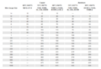
Thus, using a chart like this:
1677602446714.png

I arrived at #1 SER copper wire because 0.8 x 130amps = 104 amps - just enough to carry 100 amp load at 75C on my feeder while adhering to the NEC 80% rule.

Are you suggesting the 80% rule doesn't apply to the feeder (i.e. it's not considered a branch circuit)? If so, it looks like I can use #3 SER copper, yes??? (I'd likely still upsize to #2 or #1, as I understand the failure/heat risks associated with carrying too much current on an undersized wire.)
 
Last edited:
With that new info, do you concur?
Yes, given the additional information, I believe the use of 75C rating is correct.

Also, you've just asked the question I was going to ask about the 80% or inverse upsizing the wire by 125% and it not being entirely clear where this applies.

Let me also ask this - where is the panel installed and what is the maximum ambient temperature in terms of electrical ratings. Two factors can require you to derate the cable - more than 3 current carrying conductors (doesn't apply as you have 3, ground doesn't count) and two - temperature above 86F.
The main panel is inside and sees a maximum ambient temperature during normal conditions of about 75F. In unusually rare conditions (e.g. HVAC break-down during a NC summer), that could be as high as 95-100F indoors (should the inside temp get as hot as outside), but in such case, yours truly would likely not be inside running much of anything (i.e. next to no power load), as I have family 4 doors down that I'd stay with until it's fixed. Given the exceptional/extraordinary nature of my > 75F example, I'm inclined to throw out the HVAC failure as a bizarre/unusual outlier and treat 75F as the maximum indoor temp.

The sub panel location is also inside -- in a basement I plan to finish. Maximum ambient there during all conditions is likely 75F, as the basement is well-insulated and never fluctuates much no matter the ambient outdoor or main floor temperature. (It's always cooler in the basement than on the main floor -- even with no HVAC plumbed to it, presently.)
 
Last edited:
I agree that in your application, you don't have a temperature derating issue.

I'm inclined to throw out the HVAC failure as a bizarre/unusual outlier and treat 75F as the maximum indoor temp.
Agreed on this too. If you were wiring a non-insulated garage or shed, that might need to be looked at, but it doesn't apply here. This sort of thing comes into play when, for example, wiring a RTU (roof top unit) AC and gets even trickier when you take into account raising the cables 12" above the roof.
 
I think I just found the answer to the 'feeder' vs 'branch circuit', but I'd like @BlackGun to confirm if his knowledge permits:

Per this, I believe the feeder from the main panel to the subpanel is NOT a branch circuit:

EDIT: This (dealing with NEC Article 210) seems to corroborate:

Apparently, "a branch circuit refers to conductors after the final over-current device". In my case the branch circuits would be a) those downstream of the breakers in the subpanel (as those are the 'final' over-current devices in the subpanel) ... and b) circuits downstream of breakers other than my feeder breaker in the main panel (as those are the 'final' over-current devices in the main panel).

If that's true/correct (i.e. the feeder is not a branch), then I'm on board with #2 SER 4-conductor copper, as that would meet code, is upsized for safety, and it's likely cheaper than #1 SER given the price of copper.
 
Last edited:
Per this, I believe the feeder from the main panel to the subpanel is NOT a branch circuit:
Generally, speaking, a feeder has over current protection devices on both ends, a branch circuit does not. Except the odd case of, for example, a large motor as the single load, feeders are not branches.
 
Hi,
I'm hoping someone familiar with the NEC can shed some light on things that are unclear to me in the NEC regarding subpanels.

I am interested in adding two subpanels to my main panel. I do not believe the NEC precludes this, provided the following requirements are met:
  1. Sizing: The size of the main panel must be large enough to handle the combined loads of all subpanels.
  2. Ampacity: The ampacity of the wire between the main panel and subpanels must be appropriate for the total combined load and the distance traveled.
  3. Overcurrent protection: Each subpanel must be protected by an appropriately sized circuit breaker or fuse in the main panel.
  4. Grounding: All subpanels must be grounded and bonded to the main panel.
  5. Location: Subpanels must be located in a safe and accessible locations.
  6. Labeling: All subpanels and their breakers must be properly labeled to indicate their intended use.

My questions are:
  • What does it mean for subpanels to be grounded and bonded to the main panel? Is this just a connection from a main panel's ground bar to that of the subpanel, or is there something more required -- like separation of the neutral and ground bars in the subpanel (unlike in the main panel, where they are typically connected via a bus bar)?
  • What is expected of the breaker labeling to indicate intended use? Does the NEC want this label for the subpanel breaker (within the main panel) actually ON the breaker, itself ... or is an indicator in the main panel (e.g., inside the panel door) sufficient?

Any informed assistance is appreciated, thanks!
To understand the answer to the bonding question, you need to understand what the purpose of bonding is.

The purpose of bonding is to ground all components that are NOT INTENDED TO CARRY CURRENT. Things like enclosures, structures, housing of electrical tools/equipment which are metal, etc. The intent of this is, in the event any such structure, component, tool, or equipment develops an electrical short to the outer metal housing, the current from this will have a easy path to ground instead of going through the people who may be in contact with it.

Lots of people confuse the neutral (which is, in fact, connected to ground potential) with bonding. The critical difference here is that the neutral is INTENDED TO CARRY CURRENT in a circuit. Neutral IS at ground potential, but the moment you energize the component (drill, light, fan, saw, etc.) the current from the hot lead now travels through the neutral lead to complete the circuit...this is what is meant when I say that the neutral is intended to carry current.


When you wire up an electrical breaker box, the GROUND bus is tied directly to ground. The NEUTRAL bus is tied (bonded) to the GROUND bus (which provided your ground return path for your electrical circuits) and all neutral connections go to this bus ONLY. All your ground connections in the receptacles are tied directly to the GROUND bus and NOT the NEUTRAL bus.

Some people can't get past this, since GROUND and NEUTRAL are electrically at the same potential. Just remember: the GROUND bus is NOT INTENDED TO CARRY CURRENT UNDER NORMAL USE. The NEUTRAL bus, however, IS.


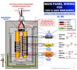
NOW...when you connect a sub panel, you MUST BREAK THE BOND BETWEEN THE GROUND AND NEUTRAL inside the sub-panel. The reason why is that when you bond your sub-panel to the main panel, you ONLY WANT YOUR NEUTRAL BONDED TO GROUND IN ONE LOCATION, AND THAT'S AT THE MAIN PANEL GROUND BUS. Your NEUTRAL buses can only ever be bonded at one point.

SO...what you do is first disconnect the bond between GROUND and NEUTRAL in your sub-panel. Then connect the GROUND bus of your sub-panel to the GROUND bus of your main panel and then ground BOTH ends (at the main panel and the sub panel). Your NEUTRAL in the main panel remains bonded to the GROUND in the main panel...and the NEUTRAL in your sub-panel will be connected to the NEUTRAL in your main panel.

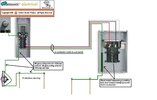
See the two images below. The first is a main panel wiring job. The second includes a sub-panel. Follow the wiring for the neutral and ground connections, and look at the bonding strap between the GROUND and the NEUTRAL bus.

EDIT:

To clarify, the second image below (showing the sub-panel wiring) is for a sub-panel located in a building detached from the one the main panel is in. In this case, the grounds are tied together AND grounded at both ends.

Additional grounding via grounding rods located at the sub-panel is NOT required if the sub-panel is located in the SAME building as the main panel. However, it must still be connected to the main panel by 4-conductor feeder cable.


I'm not sure there is any specific labeling requirement like you're talking about. The label can be physically located next to the breaker or on a label plate inside the cover: there isn't anything which specifies one or the other. Here's what the code says:

408.4(A) Circuit Directory or Circuit Identification. Every circuit and circuit modification shall be legibly identified as to its clear, evident, and specific purpose or use. The identification shall include an approved degree of detail that allows each circuit to be distinguished from all others.

Spare positions that contain unused overcurrent devices or switches shall be described accordingly. The identification shall be included in a circuit directory that is located on the face or inside of the panel door in the case of a panelboard and at each switch or circuit breaker in a switchboard or switchgear. No circuit shall be described in a manner that depends on transient conditions of occupancy.


Main Panel Wiring.jpg

Proper grounding of sub-panel.jpg
 
Last edited:
@RetiredUSNChief
Thank you for the added bonding info/explanation!

@noway2,
Thank you for helping me work through the potential gotchas I'd have otherwise failed to consider.

@BlackGun,
Thank you for that confirmation on the feeder not being considered a branch and on the lack of need to derate


#2 4-conductor SER copper wire it is. Lowe's seems to have only aluminum SER (near me, anyway), so now I'm on the hunt for something local by the foot in copper. Strangly enough, it may cost me more for #2 CU than #1 CU if I end up buying online (due to minimum length requirements being larger on the #2 than on the #1 ... at the first place I ran across).

Thankfully, this is the easy part -- but as it's copper, my wallet will surely disagree.
 
Last edited:
Do you need 4 conductors? Your home should be single phase power? Two hots, one neutral, and one ground, 3 conductors, plus a ground. Or I'm I missing something? I'd still go with #1 gauge copper wire. You need 130 amp rating wire for a 100 amp sub panel. And like @RetiredUSNChief said you must have separate bonds for your neutral and ground in your sub panel.
 
Last edited:
Simple language- leave the green bonging screw out that comes with the sub panel. That bonds neutral and ground. Code is written for lawyers.
1677606829086.png

Do you need 4 conductors? Your home should be single phase power? Two hots, one neutral, and one ground, 3 conductors, plus a ground. Or I'm I missing something? I'd still go with #1 gauge copper wire. You need 130 amp rating wire for a 100 amp sub panel. And like @RetiredUSNChief said you must have separate bonds for your neutral and ground in your sub panel.
Use of the word 'conductor' was my ignorance showing. It's 3 conductors plus a ground that I need -- meaning I want 4 wires in the SER CU. I thought we just collectively determined, above, that #3 CU is fine at 75C inside at 75F ambient as the 80% NEC rule doesn't apply to feeders -- meaning 130A rating shouldn't be needed. (It won't hurt anything other than my wallet, but it doesn't appear to be required...)
 
Last edited:
I use to be a commercial electrician so my knowledge of residential code is trash. I know commercial standards are higher, so I just wire everything to that standard.
I am an electrical engineer with most of my experience in industrial facilities and equipment. Residential standards absolutely make me want to pull my face off. I'd rather spend the few extra dollars and do things like run wires neatly and with 90 degree angles than take the shortest run in some catty-Wampus direction.
 
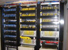
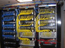
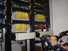
@noway2 While not directly related to the subpanel inquiry, this example of my handiwork from some years back will give you an idea of how I like my wiring (and pretty much everything else) -- and may help explain why I'm trying hard to do this right (i.e. in accordance with code).

This is color-coded (blue is telecom, yellow is data, red is an interconnect ... both on the panels and in the overhead chase) and routed through a management system, with every cable cut to length (i.e. hand-fashioned) for the needed run and then tested.

panel.jpg

panel-unconvered.jpg

switches.jpg
 
I am an electrical engineer with most of my experience in industrial facilities and equipment. Residential standards absolutely make me want to pull my face off. I'd rather spend the few extra dollars and do things like run wires neatly and with 90 degree angles than take the shortest run in some catty-Wampus direction.

That's because you know who's likely to be the one having to work on the electrical system at some point in the future!
 
That's because you know who's likely to be the one having to work on the electrical system at some point in the future!
That, sir, is EXACTLY what drives me to do work like the above, as well. Tracing and adjusting things in the above is a snap compared to in a server room that looks like a bowl of spaghetti.
 
@surrealone You do good work!

One of our division where I work has a dark fiber network over a fairly large area. It grew up organically over time and I was pulled in to help "map" the connections from device end point through the fiber network to where it terminated at an Ethernet switch port. Earlier efforts involved trying to pull the plug and see what device went away, but despite countless hours they didn't get very far.

I came up with an idea to let the switches tell us what devices were associated with which port and then use the MAC address as the key to run a scan and coordinate it to an IP address which would then tell us the device and location. However, we ran into some oddities involving missing data packets where devices would come and go instead of being consistent. What was really weird is that you could ping a particular device from one subnet and get a completely different error rate than pinging it from a different subnet but all of the subnets are just logical extensions on the same hardware. So, it looked like both a physical and logical issue depending on how you analyze it. Going into the main server room, though, yeah, the rack was a bowl of spaghetti and one of the suggestions was to simply take it all apart and redo it - someday.
 
That, sir, is EXACTLY what drives me to do work like the above, as well. Tracing and adjusting things in the above is a snap compared to in a server room that looks like a bowl of spaghetti.

If I were to ever actually build our own house, I'd also be using cable tags. That's the Navy in me!

Also, I'd label every receptacle and light switch on the back of their respective cover plates as to what breaker circuit their associated with.

Each place my wife and I moved into while I was in the Navy I would take a lamp and extension cord with me before we cluttered everything up. I'd find the breaker panel and then use the lamp to figure out exactly where every receptacle and light switch was powered from and make sure the breaker panel was accurately labeled. It's about an hour's worth of time that's well spent.
I use a radio. I have a Klein circuit tracer but it only gets you with a couple breakers. No running to rooms with a blasting rap song.
 
@surrealone You do good work!

One of our division where I work has a dark fiber network over a fairly large area. It grew up organically over time and I was pulled in to help "map" the connections from device end point through the fiber network to where it terminated at an Ethernet switch port. Earlier efforts involved trying to pull the plug and see what device went away, but despite countless hours they didn't get very far.

I came up with an idea to let the switches tell us what devices were associated with which port and then use the MAC address as the key to run a scan and coordinate it to an IP address which would then tell us the device and location. However, we ran into some oddities involving missing data packets where devices would come and go instead of being consistent. What was really weird is that you could ping a particular device from one subnet and get a completely different error rate than pinging it from a different subnet but all of the subnets are just logical extensions on the same hardware. So, it looked like both a physical and logical issue depending on how you analyze it. Going into the main server room, though, yeah, the rack was a bowl of spaghetti and one of the suggestions was to simply take it all apart and redo it - someday.
Thanks, I try.
The error rate issue sounds like a symptom from a VLAN-related problem. Someone could also have introduced a loop in the network admist the spaghetti. Never fun. I documented the above work with a spreadsheet of device/port-to-panel mappings so that if a user called the helpdesk with a network or telecom problem, the answering tech could ask for the drop number off the data or telecom jack, cross-reference that with the relevant device/port, and then check on the relevant switching device to see what was going on with that port in a matter of seconds -- no tech/IT visit to the cube needed.

If I were to ever actually build our own house, I'd also be using cable tags. That's the Navy in me!

Also, I'd label every receptacle and light switch on the back of their respective cover plates as to what breaker circuit their associated with.

Each place my wife and I moved into while I was in the Navy I would take a lamp and extension cord with me before we cluttered everything up. I'd find the breaker panel and then use the lamp to figure out exactly where every receptacle and light switch was powered from and make sure the breaker panel was accurately labeled. It's about an hour's worth of time that's well spent.
With good documentation, I've found tags aren't needed AS LONG AS it all stays organized/tidy after initial setup ... and the documentation remains up to date. (That's easy when it's entirely your show; not so much when a buncha yahoos you work with throw flies in the ointment, I know.)

When I bought this house, I traced each outlet, too (much as you do). I keep my panel's "label" in a spreadsheet that is laid-out such that it visually represents each panel slot location (including whether it's single or double pole) and each breaker's amperage. I also document in that sheet whether a breaker is GFCI (no AFCI here) and exactly what outlets are on that breaker. As I've done reno in the home and things have changed over time, I've updated the sheet -- and when I do, I print it out on an 8.5"x11" magnetic sheet meant to be used in a printer ... and then cut it down (since it doesn't take up the full page sheet) and place the result inside the door of the main panel.

Nice, clean, and easily updated...

EDIT:
I use a radio. I have a Klein circuit tracer but it only gets you with a couple breakers. No running to rooms with a blasting rap song.
I never could cost-justify one of those (the tracer) for personal use.
 
Last edited:
For posterity's sake, I ended up going with #1 CU SER (1-1-1-3). It was only nominally more expensive than #2 once I found a place that didn't have ridiculous minimum lengths, and I figured it to be cheap peace of mind. (Box stores within 1 hour of me all had only AL SER, so I had to order online as I wanted CU.)
 
Just an FYI from a duffus that used to teach some NEC classes. Your local AHJ has all the authority regardless of what the NEC code says. Even if he is wrong and an idiot. Wouldn’t be a bad idea to check with the local Code enforcement officer. Might save you a headache later. Especially if you ever sell the property.
 
For posterity's sake, I ended up going with #1 CU SER (1-1-1-3). It was only nominally more expensive than #2 once I found a place that didn't have ridiculous minimum lengths, and I figured it to be cheap peace of mind. (Box stores within 1 hour of me all had only AL SER, so I had to order online as I wanted CU.)
Smart move. In general, I prefer copper. AL if not used with proper lugs (brass) can cause fires. I prefer to be safe.
 
Just an FYI from a duffus that used to teach some NEC classes. Your local AHJ has all the authority regardless of what the NEC code says. Even if he is wrong and an idiot. Wouldn’t be a bad idea to check with the local Code enforcement officer. Might save you a headache later. Especially if you ever sell the property.
Verify that what you’re doing is within the legal spec of not needing to pull a permit. Once you’re in the clear, then consider asking. If approached right, they’ll likely help you.

I mentioned residential standards driving me nuts. When building my wife’s shop, I had several concerns about the wiring done by an electrician hired by the GC that abandoned the job. Having taken some code classes he taught, I got the retired Durham county inspector to give the site a once over as a favor. He said it met code, but understood that with my industrial background that it would drive me nuts.
 
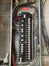
I wish I had a before and after of my house panel. It was a total disaster of wires on 40 circuits. It was so bad it was impossible to find wires in common romex wire or get a screwdrive on a terminal. I looked at it for years and decided I wasn’t getting paid for my own house and ignored it until I changed out a a meter to a combination meter/panel for adding a generator receptacle. Here is the after. You have to remember the code has drastically changed since 1990 for bringing in wires into the panel. You can’t bundle wires at the top like this anymore. Believe me this is a massive improvement.

1677636696338.jpeg
 
Just an FYI from a duffus that used to teach some NEC classes. Your local AHJ has all the authority regardless of what the NEC code says. Even if he is wrong and an idiot. Wouldn’t be a bad idea to check with the local Code enforcement officer. Might save you a headache later. Especially if you ever sell the property.
Unless the house inspector they hire is an electrician they don’t know anything except what someone told them in classes. When a house was built it was on the codes of that era. If someone told me I had to separate all the wires and started quoting current code I would tell them I would at their expense. Too many people spend thousands after a house inspector writes a report. If it didn’t burn down under the old codes it is most likely ok. But there is always the home owners who had stuff added by some guy who does it without experience or permits.
 
@BlackGun - I, too, wish I had a before/after. Mine looks a lot like the above minus the bundled entry... now. However, when I bought the place, it had:
  • Loose main lugs thanks to the AL SER expanding/contracting over the years;
  • Several SquareD breakers in my Crouse-Hinds panel for which they aren't approved;
  • Neutral as well as ground wires sharing termination locations on the bus bars in excess of what the panel's labeling indicates is permissible for a single termination point;
  • A cheater/tandem breaker in the panel, whose labeling does not indicate tandem breakers are permissible
@CZfool68 - No argument regarding who has authority and that even idiots may have it. If I had faith in the local yocals, I would run with your suggestion. That said, I've seen crap on/in this property (and in this neighborhood on neighbors' relatively new properties) that boggles the mind as to how it ever passed initial inspection. So ... I basically have zero faith in my local department of inspections.

@noway2 -- I'm old school and find copper to be worth paying for -- if nothing else because it doesn't seem to work itself loose due to expansion/contraction. (If it does, I've never seen it do so...)
 
Did you know that most jurisdictions are having up to 20 inspections per man per day. I can’t even imagine a 8 hour shift doing 20 stops. No way a proper inspection takes place. Some large counties are even doing virtual inspections with a company tech on Facetime. I’ve had inspectors ask me about the codes in their first couple years. Can you image very rural low density counties where they have like 2 or 3 inspectors doing everything from footings, concrete slabs, framing, HVAC, plumbing, and electrical? Not possible.
 
Back
Top Bottom